 Find out by following these steps: The point of reference for all signals is the terminal (or PC).
- Measure the DC voltages between (DB25) pins 2 & 7 and between pins 3 & 7. Be sure the black lead is connected to pin 7 (Signal Ground) and the red lead to whichever pin you are measuring.
- If the voltage on pin 2 (TD) is more negative than -3 Volts, then it is a DTE, otherwise it should be near zero volts.
- If the voltage on pin 3 (RD) is more negative than -3 Volts, then it is a DCE.
- If both pins 2 & 3 have a voltage of at least 3 volts, then either you are measuring incorrectly, or your device is not a standard EIA-232 device. Call technical support.
- In general, a DTE provides a voltage on TD, RTS, & DTR, whereas a DCE provides voltage on RD, CTS, DSR, & CD.
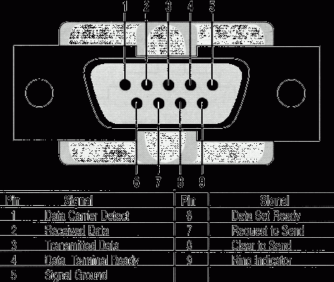
Data is transmitted and received on pins 2 and 3 respectively. Data Set Ready (DSR) is an indication from the Data Set (i.e., the modem or DSU/CSU) that it is on. Similarly, DTR indicates to the Data Set that the DTE is on. Data Carrier Detect (DCD) indicates that a good carrier is being received from the remote modem.
Pins 4 RTS (Request To Send - from the transmitting computer) and 5 CTS (Clear To Send - from the Data set) are used to control. In most Asynchronous situations, RTS and CTS are constantly on throughout the communication session. However where the DTE is connected to a multipoint line, RTS is used to turn carrier on the modem on and off. On a multipoint line, it’s imperative that only one station is transmitting at a time (because they share the return phone pair). When a station wants to transmit, it raises RTS. The modem turns on carrier, typically waits a few milliseconds for carrier to stabilize, and then raises CTS. The DTE transmits when it sees CTS up. When the station has finished its transmission, it drops RTS and the modem drops CTS and carrier together.
Clock signals (pins 15, 17, & 24) are only used for synchronous communications. The modem or DSU extracts the clock from the data stream and provides a steady clock signal to the DTE. Note that the transmit and receive clock signals do not have to be the same, or even at the same baud rate.
Note: Transmit and receive leads (2 or 3) can be reversed depending on the use of the equipment - DCE Data Communications Equipment or a DTE Data Terminal Equipment.
Updated On: 15.02.19